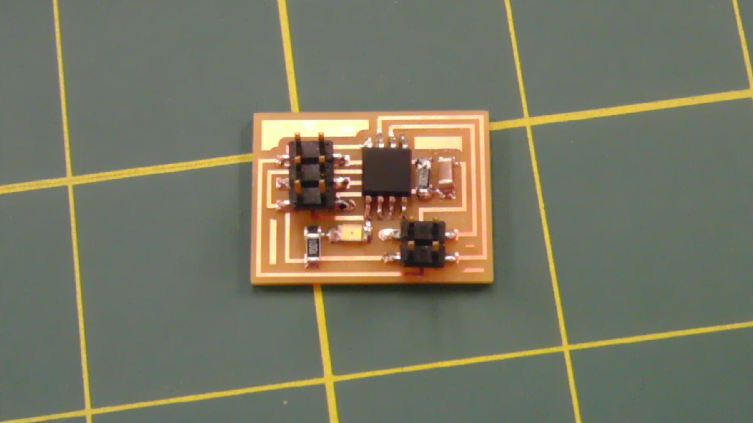
Assignment: Add an output device to a microcontroller board and program it to do something.
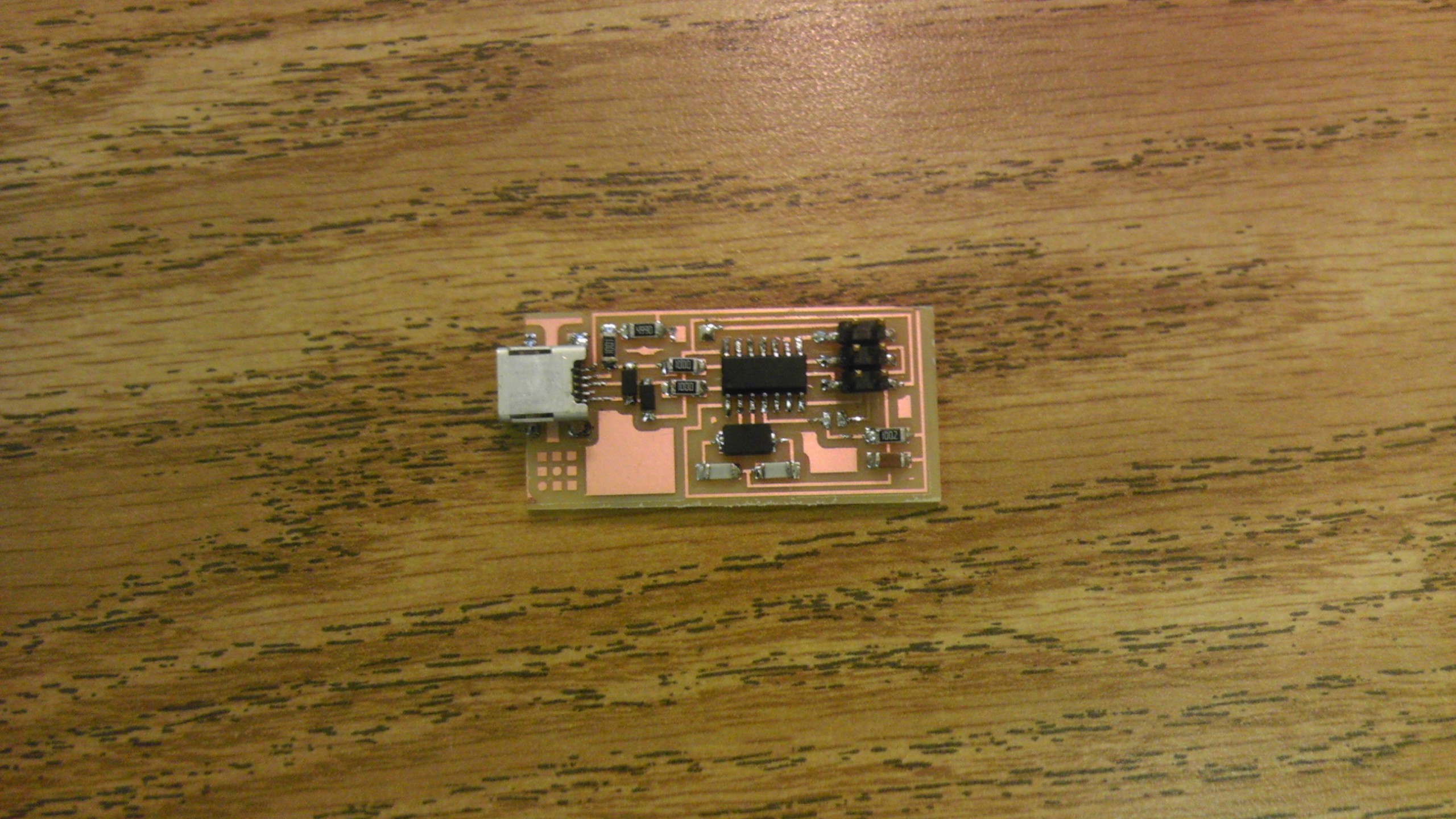
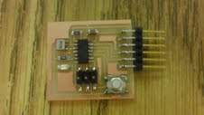
For this assignment, I decided to work with the DC and Servo motors because these types of motors will be beneficial for my final project. Below are images for each board's traces that I milled using the Roland Modela and their end results (after soldering).
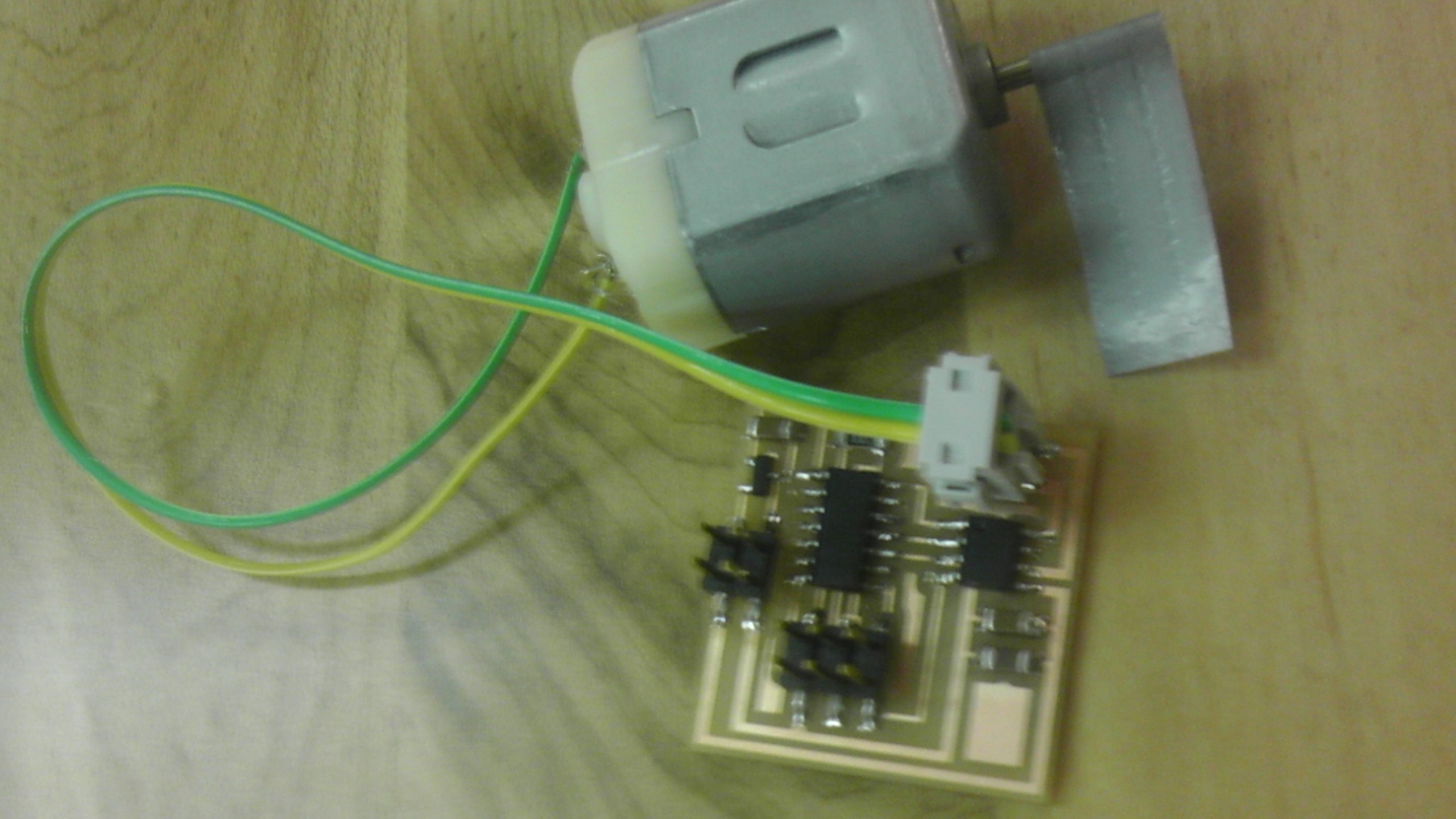
DC Motor

Servo Motor
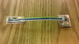
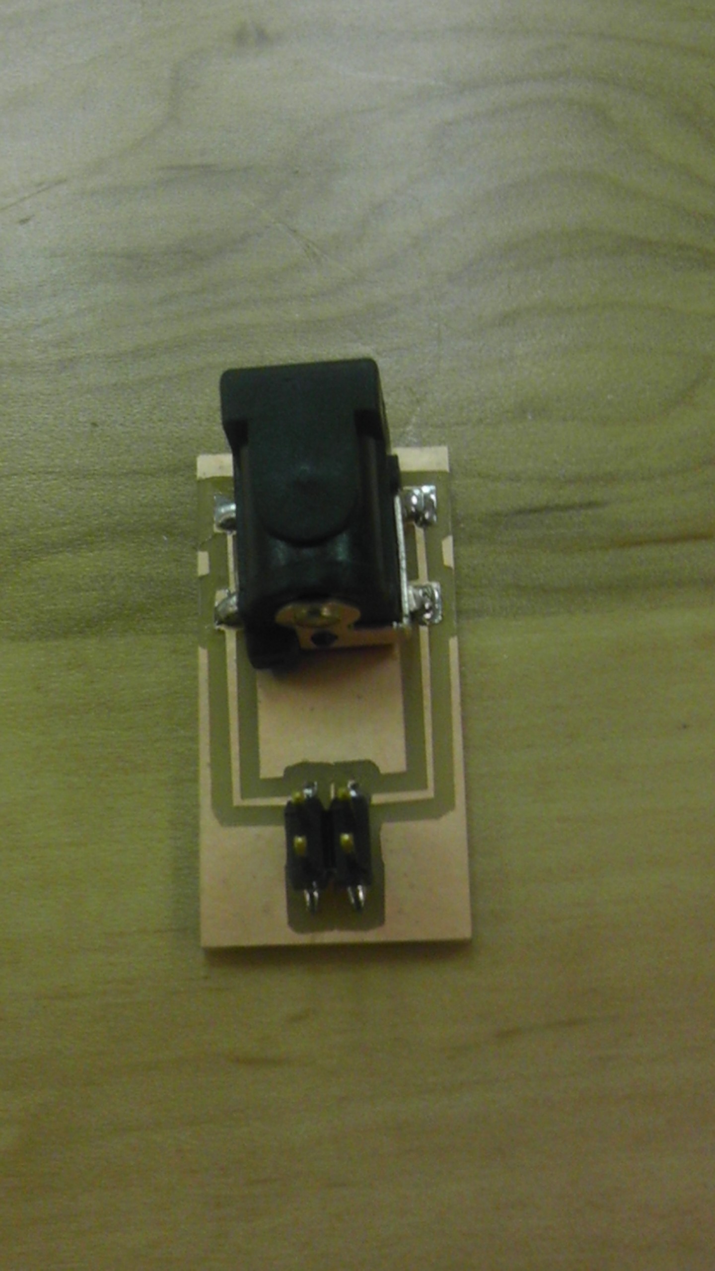
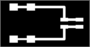
After successfully soldering both boards, I also created a power source so that once each board and motor were connected and programmed, the motors would run. Below are images of the finished power source and trace ( using a 4-pin header) that I use in order to power my boards. Next, I attempted to program both boards in Windows with the WinAVR program--that we used for Embedded Programming week. Unfortunately, I had some trials, receiving error messages stating, "Could not find USBtiny device" or "initialization failed, Double check connections and try again". After some investigation, I figured out that at this point with the use of multiple ribbon cables, one needs to be sure that 1.GND and VCC are connected to the right pins, 2. if wires are needed with motors (i.e. a DC Motor), be sure to be able to recognize the HIGH and LOW, and 3. If operating in Windows and the program continues to give the message of not being able to find the USBtiny device, try plugging and unplugging and/or interchanging the port that you plug your USB in. Also below are images of confirmation once my boards were programmed.
After successfully programming my boards with the C File on the Fab Website, I made some changes to see what the motors would do. Below are videos and links to my updated C Files.

